This page is Bobby approved and follows the guidelines of the Web Accessibility Initiative for use by the disabled
| THE SCHENECTADY DIGITAL HISTORY ARCHIVE a service of the Schenectady County Public Library |
| Railroads |
Home |
Search Local History |
Contact Us |
SCPL Home |
[Note: Images of each page (averaging 60-80K) are provided at their original size in the contents area. Illustrations are included in original and enlarged sizes within the text.]
[Cover] | [Title Page]
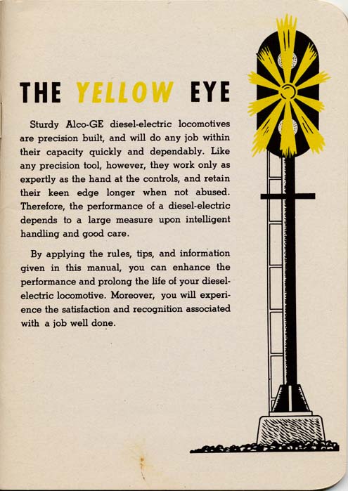
[Page 3] THE YELLOW EYE
Sturdy Alco-GE diesel-electric locomotives are precision built, and will do any job within their capacity quickly and dependably. Like any precision tool, however, they work only as expertly as the hand at the controls, and retain their keen edge longer when not abused. Therefore, the performance of a diesel-electric depends to a large measure upon intelligent handling and good care.
By applying the rules, tips, and information given in this manual, you can enhance the performance and prolong the life of your diesel-electric locomotive. Moreover, you will experience the satisfaction and recognition associated with a job well done.
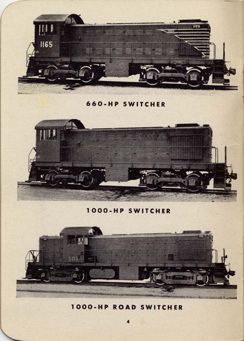
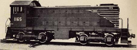
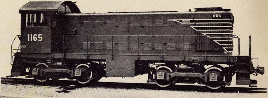
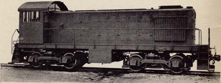
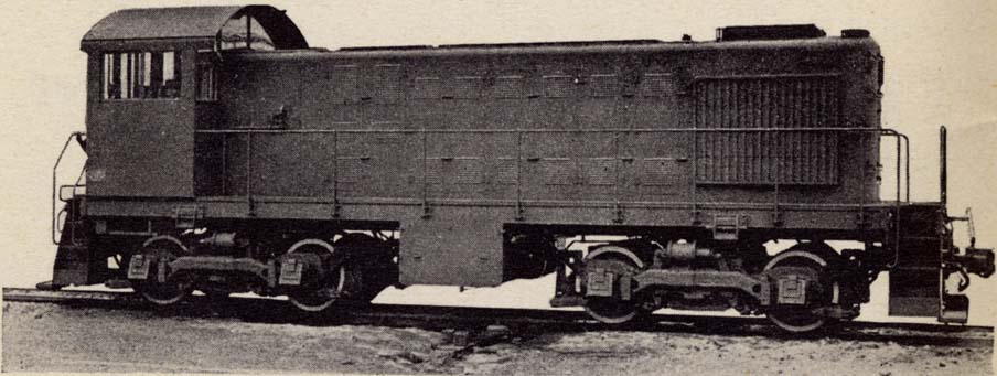
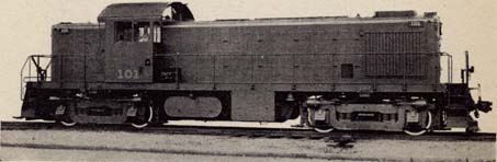
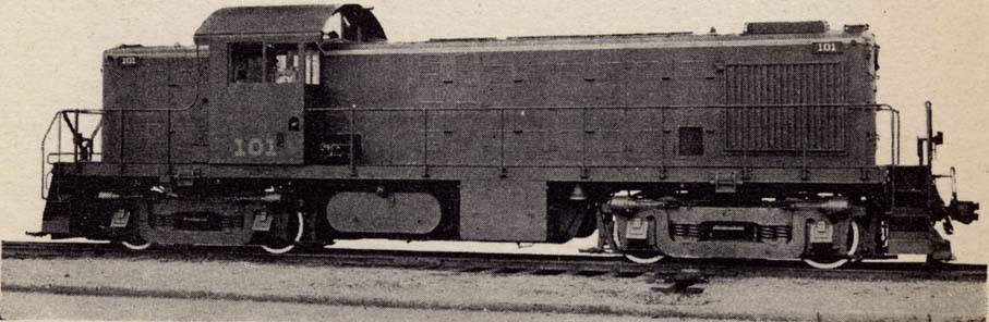
[Page 4] Photos of 660-HP Switcher [1x | 4x], 1000-HP Switcher [1x | 4x], 1000-HP Road Switcher [1x | 4x]
[Page 5]
| Subject | Pages | Page Images |
| Clearance Diagrams - Haulage Capacity | 6-8 | 6, 7, 8 |
| How a Diesel-Electric Functions | 9 | 9 |
| Controls at Engineman's Position | 10-11 | 10, 11 |
| Other Operating Controls | 12-15 | 12, 13, 14, 15 |
| How to Operate Your Diesel Electric | 16-17 | 16, 17 |
| Throttle Operation and Controller Positions | 18-19 | 18, 19 |
| Operating Tips | 20-21 | 20, 21 |
| Operating Gages and Automatic Safeguards | 22-23 | 22, 23 |
| Location of Fuses | 24-25 | 24, 25 |
| Diesel Engine | 26-27 | 26, 27 |
| Fuel-oil System | 28-29 | 28, 29 |
| Lubricating-oil System | 30-31 | 30, 31 |
| Cooling-water System | 32-33 | 32, 33 |
| Pressure-air System | 34-35 | 34, 35 |
| Controls and Operation of Multiple-unit Locomotives | 36-39 | 36, 37, 38, 39 |
| Unusual Operating Conditions | 40-47 | 40, 41, 42, 43, 44, 45, 46, 47 |
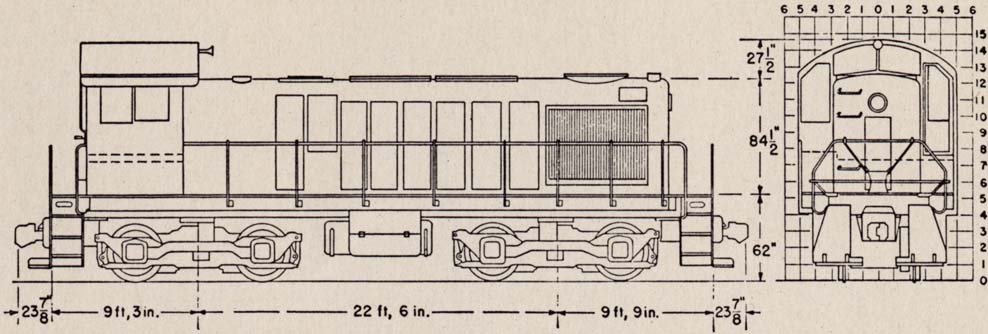
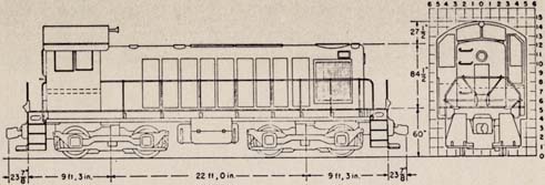
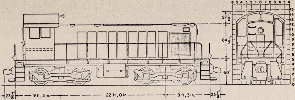
1000-HP SWITCHER [Diagrams 1x | 4x]
115 Tons on Drivers
60 MPH Maximum Speed
One GT-553 Generator; Four GE-731 Motors; 75:16 Gear Ratio; 40-in. Wheels
TRAILING TONS* IT WILL HAUL SAFELY
Speed   Tractive    Time         GRADE - COMPENSATED FOR CURVATURE
 MPH     Effort     Limit  Level   0.5%   1.0%   1.5%   2.0%  2.5%  3.0%

  5.0    50,000     4 min.  ....   3325   1925   1335   1010   805   660
  7.5    36,500    90 min.  ....   2385   1370    940    705   555   450
 10.0    28,000    90 min.  5765   1790   1020    695    514   400   320
 15.0    19,800     Cont.   3805   1210    680    455    328   248   190
 20.0    15,000     Cont.   2640    864    480    310    218   158   115
 25.0    12,000     Cont.   1905    644    350    220    149   100    69
 30.0    10,000     Cont.   1435    495    266    160    100    63   ...
 35.0     8,100     Cont.   1030    360    185    104     58   ...   ...
 40.0     6,600     Cont.    730    255    120     59   ....   ...   ...
* Based on Davis train resistance formulae for standard 4-axle cars with an average weight per car of 40 tons.
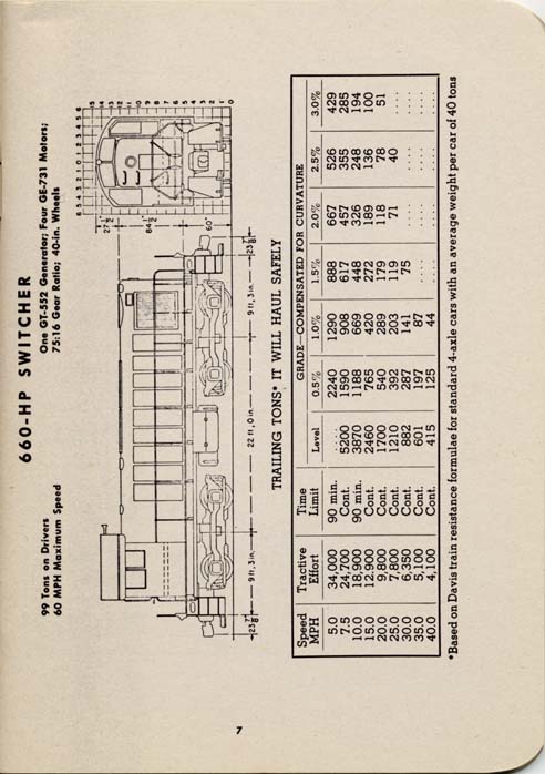
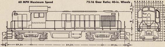
660-HP SWITCHER [Diagrams 1x | 4x]
99 Tons on Drivers
60 MPH Maximum Speed
One GT-552 Generator; Four GE-731 Motors; 75:16 Gear Ratio; 40-in. Wheels
TRAILING TONS* IT WILL HAUL SAFELY
Speed   Tractive    Time         GRADE - COMPENSATED FOR CURVATURE
 MPH     Effort     Limit  Level   0.5%   1.0%   1.5%   2.0%  2.5%  3.0%

  5.0    34,000    90 min.  ....   2240   1290    888    667   526   429
  7.5    24,700     Cont.   5200   1590    908    617    457   355   285
 10.0    18,900    90 min.  3870   1188    669    448    326   248   194
 15.0    12,900     Cont.   2460    765    420    272    189   136   100
 20.0     9,800     Cont.   1700    540    289    179    118    78    51
 25.0     7,800     Cont.   1210    392    203    119     71    40   ...
 30.0     6,350     Cont.    882    287    141     75    ...   ...   ...
 35.0     5,100     Cont.    601    197     87    ...    ...   ...   ...
 40.0     4,100     Cont.    415    125     44    ...    ...   ...   ...
* Based on Davis train resistance formulae for standard 4-axle cars with an average weight per car of 40 tons.
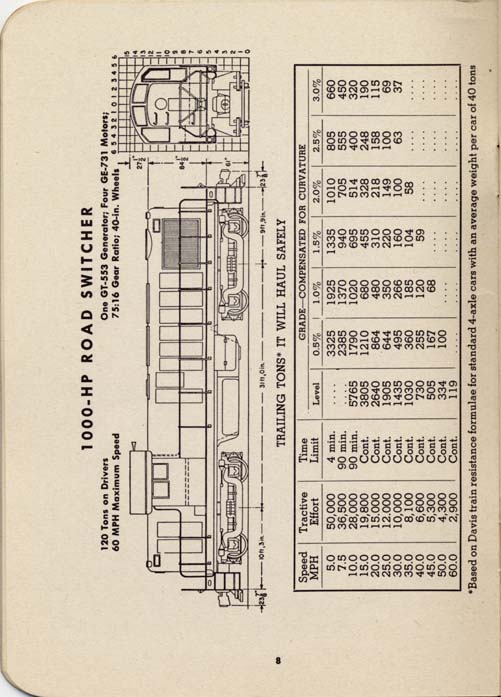
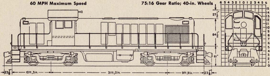
1000-HP ROAD SWITCHER [Diagrams 1x | 4x]
120 Tons on Drivers
60 MPH Maximum Speed
One GT-553 Generator; Four GE-731 Motors; 75:16 Gear Ratio; 40-in. Wheels
TRAILING TONS* IT WILL HAUL SAFELY
Speed   Tractive    Time         GRADE - COMPENSATED FOR CURVATURE
 MPH     Effort     Limit  Level   0.5%   1.0%   1.5%   2.0%  2.5%  3.0%

  5.0    50,000     4 min.  ....   3325   1925   1335   1010   805   660
  7.5    36,500    90 min.  ....   2385   1370    940    705   555   450
 10.0    28,000    90 min.  5765   1790   1020    695    514   400   320
 15.0    19,800     Cont.   3805   1210    680    455    328   248   190
 20.0    15,000     Cont.   2640    864    480    310    218   158   115
 25.0    12,000     Cont.   1905    644    350    220    149   100    69
 30.0    10,000     Cont.   1435    495    266    160    100    63    37
 35.0     8,100     Cont.   1030    360    185    104     58   ...   ...
 40.0     6,600     Cont.    730    255    120     59   ....   ...   ...
 45.0     5,300     Cont.    505    167     68    ...   ....   ...   ...
 50.0     4,300     Cont.    334    100   ....    ...   ....   ...   ...
 60.0     2,900     Cont.    119   ....   ....    ...   ....   ...   ...
* Based on Davis train resistance formulae for standard 4-axle cars with an average weight per car of 40 tons.
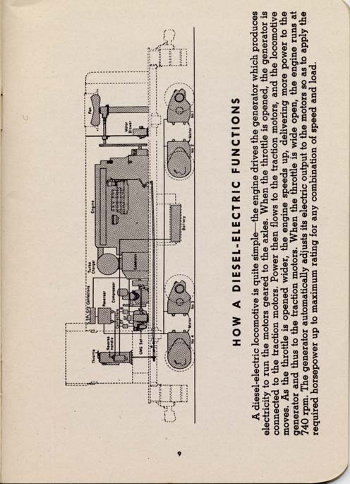
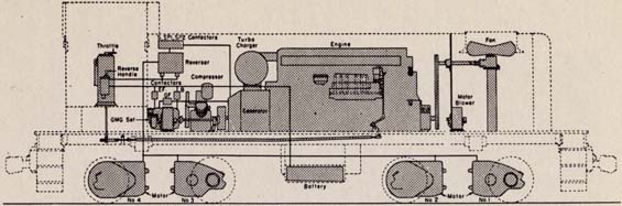
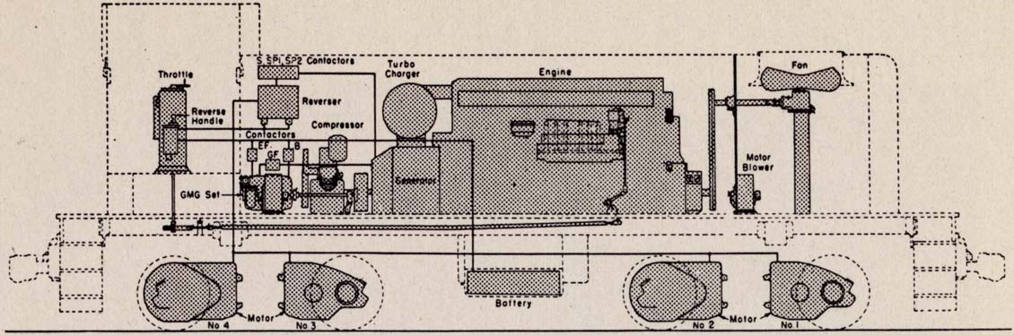
A diesel-electric locomotive is quite simple - the engine drives the generator which produces electricity to run the motors geared to the axles. When the throttle is opened, the generator is connected to the traction motors. Power then flows to the traction motors, and the locomotive moves. As the throttle is opened wider, the engine speeds up, delivering more power to the generator and thus to the traction motors. When the throttle is wide open, the engine runs at 740 rpm. The generator automatically adjusts its electric output to the motors so as to apply the required horsepower up to maximum rating for any combination of speed and load.
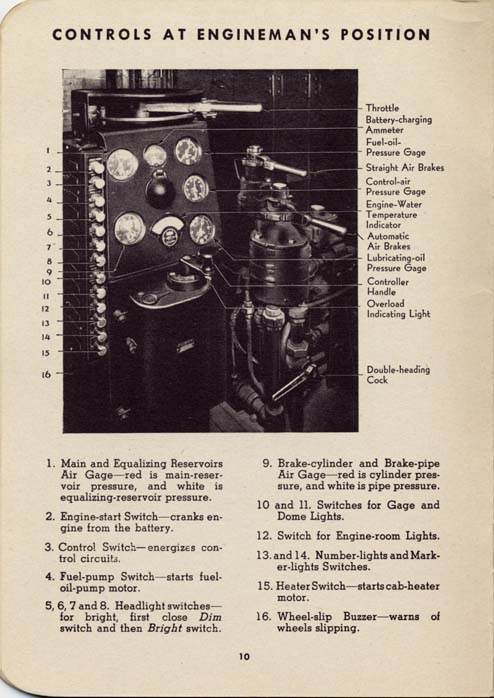
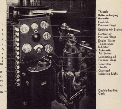
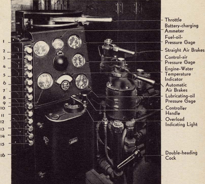
Labels: Throttle, Battery-charging Ammeter, Fuel-oil Pressure Gage, Straight Air Brakes, Control-air Pressure Gage, Engine-Water Temperature Indicator, Automatic Air Brakes, Lubricating-oil Pressure Gage, Controller Handle, Overload Indicating Light
Numbered labels:
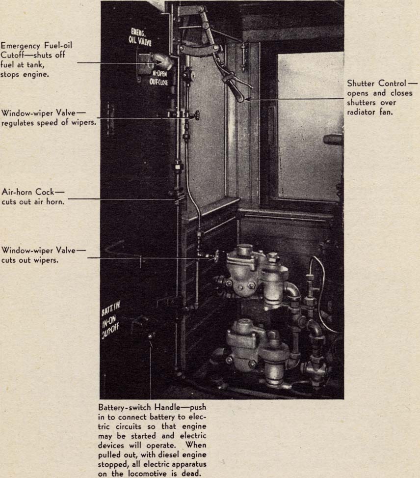
Labels:
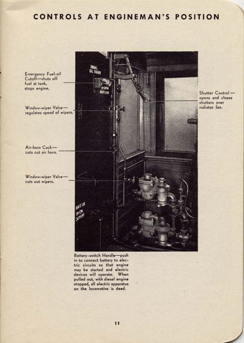
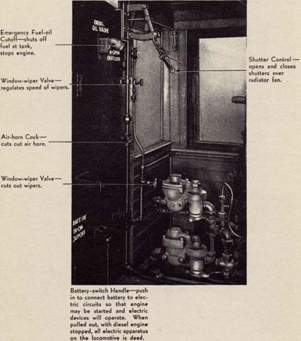
Emergency Fuel-oil Cutoff - shuts off fuel at tank, stops engine.
Shutter Control - opens and closes shutters over radiator fan.
Window-wiper Valve - regulates speed of wipers.
Air-horn Cock - cuts out air horn.
Window-wiper Valve - cuts out wipers.
Battery-switch Handle - push in to connect battery to electric circuits so that engine may be started and electric devices will operate. When pulled out, with diesel engine stopped, all electric apparatus on the locomotive is dead.
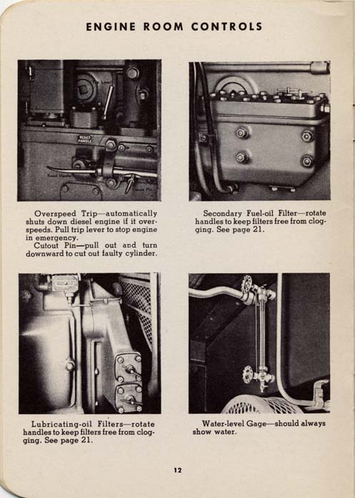
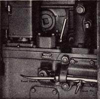
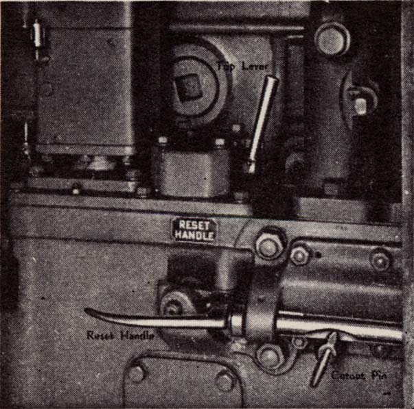
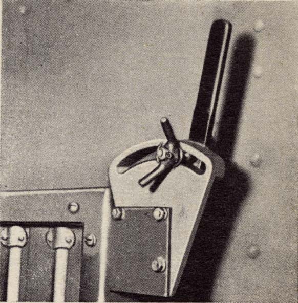
Overspeed Trip - automatically shuts down diesel engine if it overspeeds. Pull trip lever to stop engine in emergency.
Cutout Pin - pull out and turn downward to cut out faulty cylinder.
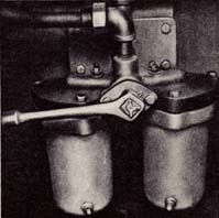
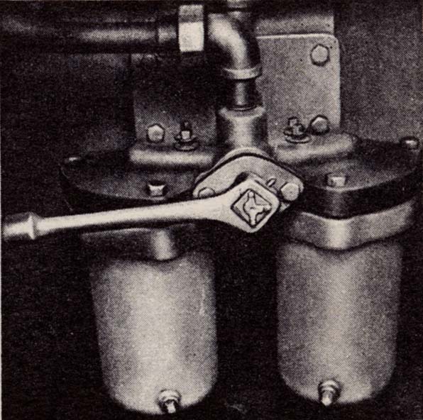
Secondary Fuel-oil Filter - rotate handles to keep filters free from clogging. See page 21.
Lubricating-oil Filters - rotate handles to keep filters free from clogging. See page 21.
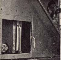
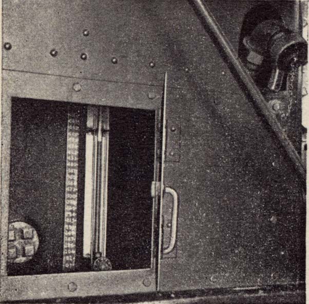
Water-level Gage - should always show water.
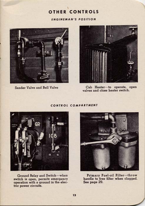
ENGINEMAN'S POSITION
Sander Valve and Bell Valve
Cab Heater - to operate, open valves and close heater switch.
CONTROL COMPARTMENT
Ground Relay and Switch - when switch is open, permits emergency operation with a ground in the electric power circuits.
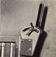
Primary Fuel-oil Filter - throw handle to free filter when clogged. See page 29.
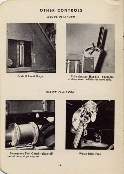
ABOVE PLATFORM
Fuel-oil Level Gage
Side-shutter Handle - operates shutters over radiator on each side.
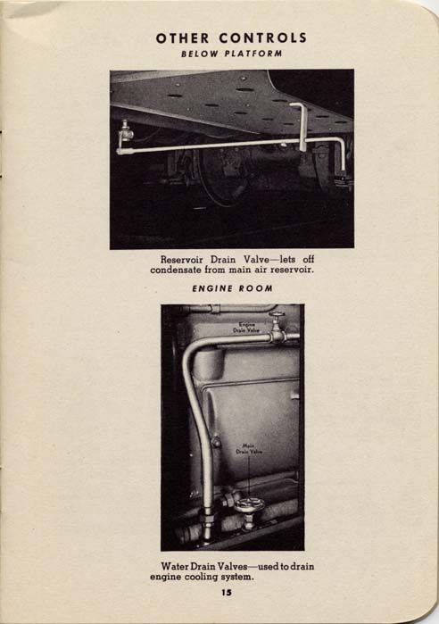
BELOW PLATFORM
Emergency Fuel Cutoff - shuts off fuel at tank, stops engine.
Water Filler Pipe
Reservoir Drain Valve - lets off condensate from main air reservoir.
ENGINE ROOM
Water Drain Valves - used to drain engine cooling system.
When taking over a diesel-electric, check the lubricating oil, fuel oil, and cooling water - see that hand valves in the water, air, and oil lines are in the proper position. Give handles on the filters in the fuel and lubricating-oil lines one turn. An inspection of engine, generator, and control compartments for cloths, tools, etc., that may have been inadvertently left near moving parts or electric connections is a worthwhile precaution.
NOTE: After engine is warm, air pressure can be built up faster by opening throttle somewhat less than halfway. Running the unloaded engine with throttle open wider is bad practice. Close throttle when air is up.
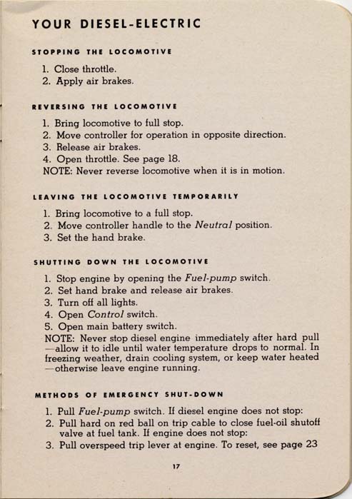
STOPPING THE LOCOMOTIVE
REVERSING THE LOCOMOTIVE
NOTE: Never reverse locomotive when it is in motion.
LEAVING THE LOCOMOTIVE TEMPORARILY
NOTE: Never stop diesel engine immediately after hard pull - allow it to idle until water temperature drops to normal. In freezing weather, drain cooling system, or keep water heated - otherwise leave engine running.
METHODS OF EMERGENCY SHUT-DOWN
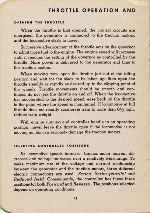
When the throttle is first opened, the control circuits are energized, the generator is connected to the traction motors, and the locomotive starts to move.
Successive advancement of the throttle acts on the governor to admit more fuel to the engine. The engine speed will increase until it reaches the setting of the governor as controlled by the throttle. More power is delivered to the generator and thus to the traction motors.
When moving cars, open the throttle just out of the idling position and wait for the slack to be taken up; then open the throttle steadily as rapidly as desired up to the slipping point of the wheels. Throttle movements should be smooth and continous; do not jerk the throttle on and off. When the locomotive has accelerated to the desired speed, ease back on the throttle to the point where the speed is maintained. If locomotive at full throttle does not readily accelerate train to more than 6 1/2 mph, reduce train weight.
With engine running and controller handle in an operating position, never leave the throttle open if the locomotive is not moving as this can seriously damage the traction motors.
SELECTING CONTROLLER POSITIONS
As locomotive speeds increase, traction-motor current decreases and voltage increases over a relatively wide range. To make maximum use of the voltage and current relationship between the generator and the traction motors, three different electric connections are used -- Series, Series-parallel and Reduced field. Consequently, the controller has these three positions for both Forward and Reverse. The positions selected depend on operating conditions.
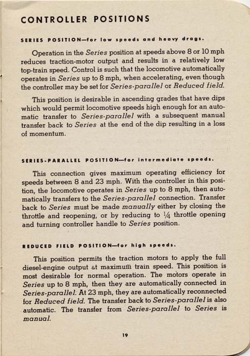
SERIES POSITION - for low speeds and heavy drags.
Operation in the Series position at speeds above 8 or 10 mph reduces traction-motor output and results in a relatively low top-train speed. Control is such that the locomotive automatically operates in Series up to 8 mph, when accelerating, even though the controller may be set for Series-parallel or Reduced field.
This position is desirable in ascending grades that have dips which would permit locomotive speeds high enough for an automatic transfer to Series-parallel with a subsequent manual transfer back to Series at the end of the dip resulting in a loss of momentum.
SERIES-PARALLEL POSITION - for intermediate speeds.
This connection gives maximum operating efficiency for speeds between 8 and 23 mph. With the controller in this position, the locomotive operates in Series up to 8 mph, then automatically transfers to the Series-parallel connection. Transfer back to Series must be made manually either by closing the throttle and reopening, or by reducing to 1/4 throttle opening and turning controller handle to Series position.
REDUCED FIELD POSITION - for high speeds.
This position permits the traction motors to apply the full diesel-engine output at maximum train speed. This position is most desirable for normal operation. The motors operate in Series up to 8 mph, then they are automatically connected in Series-parallel. At 23 mph, they are automatically reconnected for Reduced field. The transfer back to Series-parallel is also automatic. The transfer from Series-parallel to Series is manual.
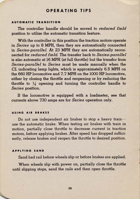
AUTOMATIC TRANSITION
The controller handle should be moved to reduced field position to utilize the automatic transition feature.
With the controller in this position the traction motors operate in Series up to 8 MPH, then they are automatically connected in Series-parallel. At 23 MPH they are automatically reconnected for reduced field. The transfer back to Series-parallel is also automatic at 16 MPH (at full throttle) but the transfer from Series-parallel to Series must be made manually when the CL indicating lamp lights, which is approximately 6.5 MPH on the 660 HP locomotive and 7.7 MPH on the 1000 HP locomotive, either by closing the throttle and reopening or by reducing the throttle to 1/4 opening and turning the controller handle to Series position.
If the locomotive is equipped with a loadmeter, see that currents above 730 amps are for Series operation only.
USING AIR BRAKES
Do not use independent air brakes to stop a heavy train - use the automatic brake. When testing air brakes with train in motion, partially close throttle to decrease current in traction motors, before applying brakes. After speed has dropped sufficiently, release brakes and reopen the throttle to desired position.
APPLYING SAND
Sand bad rail before wheels slip or before brakes are applied.
When wheels slip with power on, partially close the throttle until slipping stops, sand the rails and then open throttle.
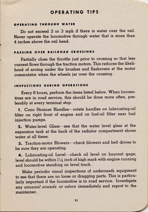
OPERATING THROUGH WATER
Do not exceed 2 or 3 mph if there is water over the rail. Never operate the locomotive through water that is more than 4 inches above the rail head.
PASSING OVER RAILROAD CROSSINGS
Partially close the throttle just prior to crossing so that less current flows through the traction motors. This reduces the likelihood of arcing under the brushes and flashovers at the motor commutator when the wheels jar over the crossing.
Every 8 hours, perform the items listed below. When locomotives are in road service, this should be done more often, preferably at every terminal stop.
Make periodic visual inspections of underneath equipment to see that there are no loose or dragging parts. This is particularly important if the locomotive is in road service. Investigate any unusual sounds or odors immediately and report to the maintainer.
GAGES
ALARMS
SAFETY DEVICES
To reset, pull out each Bosch pump cutout plunger and turn until the trip pin points straight down. Pull out on the reset handle until it latches, and then pull out and turn each plunger to engage trip pin in the notch in the rack.
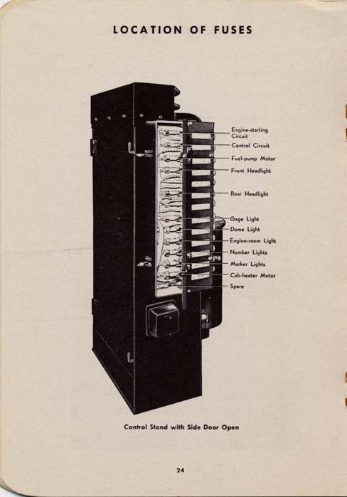
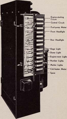
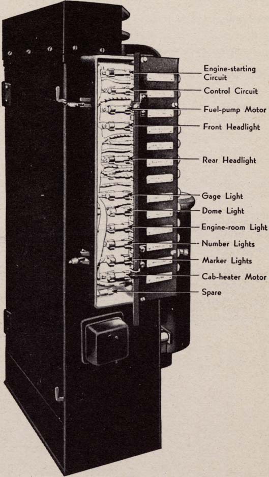
[Photo 1x | 4x] Control Stand with Side Door Open
Labels: Engine-starting Circuit, Control Circuit, Fuel-pump Motor, Front Headlight, Rear Headlight, Gage Light, Dome Light, Engine-room Light, Number Lights, Marker Lights, Cab-heater Motor, Spare
EFFECT OF BLOWN FUSES
| When Starting Up | Fuses Involved |
| Engine will not crank |
Battery circuit Engine-starting circuit Control circuit |
| Fuel Pump will not run |
Battery circuit Fuel-pump motor |
| Battery ammeter shows discharge |
Control circuit Auxiliary-generator power circuit Auxiliary-generator field |
| Locomotive will not move |
Control circuit |
| Locomotive in Operation | Fuses Involved |
| Battery ammeter continuously shows discharge |
Auxiliary-generator power circuit Auxiliary-generator field |
| Battery ammeter reads zero |
Battery circuit |
| Locomotive stops |
Control circuit |
| Diesel engine loses load |
Control circuit |
| Fuel pump stops |
Fuel-pump motor |
| Diesel engine stops |
Fuel-pump motor |
| Lights do not burn |
Respective light |
TESTING A FUSE
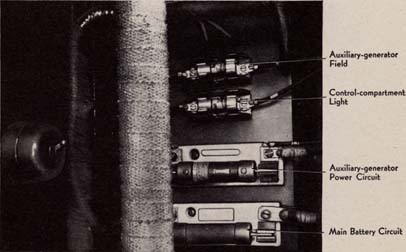
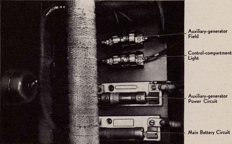
[Photo 1x | 4x] Control Compartment Fuses
Labels: Auxiliary-generator Field, Control-compartment Light, Auxiliary-generator Power Circuit, Main Battery Circuit
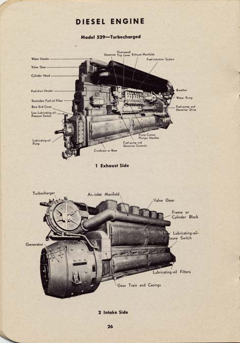
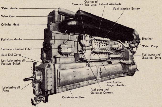
Model 539 - Turbocharged
[Photo 1x | 4x] 1 Exhaust Side
Labels: Water Header, Valve Gear, Cylinder Head, Fuel-drain Header, Secondary Fuel-oil Filter, Base End Cover, Low Lubricating-oil Pressure Switch, Lubricating-oil Pump, Governor, Overspeed Trip Lever, Exhaust Manifolds, Fuel-injection System, Breather, Water Pump, Fuel-pump and Governor Drive, Pump Cutout Plunger Handles, Fuel-pump and Governor Controls, Crankcase or Base
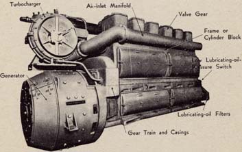
Labels: Turbocharger, Generator, Air-inlet Manifold, Valve Gear, Frame or Cylinder Block, Low Lubricating-oil Pressure Switch, Lubricating-oil Filters, Gear Train and Casings
The Alco diesel engine has six cylinders, is of the single acting type, operating on a four-stroke cycle, and develops full rated horsepower at 740 rpm. The 660-HP engine is a nonturbocharged engine; the 1000-HP engine is a turbo-charged engine using the Buchi system. The engine is started by the main generator which operates off the storage battery as a starting motor when the Engine-start button is depressed.
OPERATION OF ENGINE SHUTDOWN MECHANISM
A dump valve on the Woodward governor power cylinder is held closed by an electric solenoid. If the circuit to the solenoid is opened - by pulling out fuel-pump button or automatic operation of low lube-oil-pressure switch - the dump valve opens and the pressure on the underside of the governor power piston is relieved. This forces the Bosch fuel-pump racks into shutdown position, and the engine stops.
STOPPING ENGINE AT THE ENGINE
Pull overspeed-trip lever at the engine.
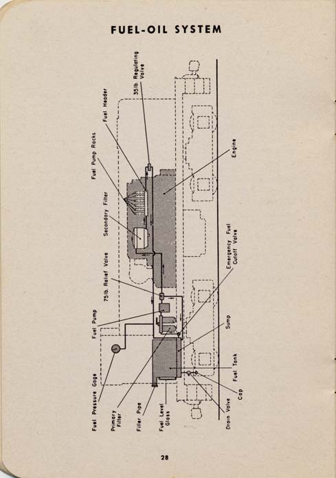
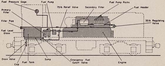
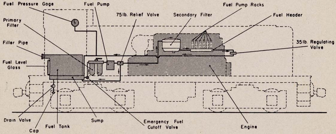
Labels: Fuel Pressure Gage, Primary Filter, Filler Pipe, Fuel Level Glass, Fuel Pump, 75lb. Relief Valve, Secondary Filter, Fuel Pump Racks, Fuel Header, 35lb. Relief Valve, Drain Valve, Cap, Fuel Tank, Sump, Emergency Fuel Cutoff Valve, Engine
FLOW OF FUEL
Fuel is drawn from main tank under cab floor through primary duplex filter to intake side of fuel pump in control compartment. Pump forces fuel through secondary filter to fuel header on bank of fuel-injection pumps. Excess fuel returns to main tank.
FILLING FUEL TANK
Run fuel oil into filler pipe at end platform and watch level gage on tank to avoid overflowing. Switchers hold 635 gallons, and road switchers 800 gallons. If no train-heat boiler is used the road-switcher boiler-water tank may be used increasing the capacity to 1600 gallons.Duplex filter in control compartment contains two units for filtering the fuel oil after it leaves the tank. Only one unit is used at a time. If the fuel-oil pressure drops below 30 lb. due to clogged filter, throw filter handle to transfer fuel flow through the clean unit. Report this action to maintainer.
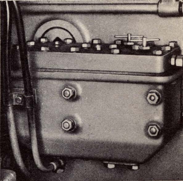
SECONDARY FILTER
Filter on left side of engine cleans the fuel oil before it reaches the fuel-injection pumps. When the fuel pressure drops below 30 lb. rotate the handles to clear filter.
PRESSURE GAGE
This should read between 30 and 50 lb. when diesel engine is running. When fuel-oil pressure is lost or reads low, refer to page 42.
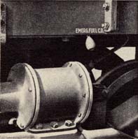
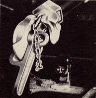
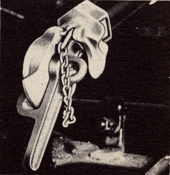
EMERGENCY FUEL CUTOFF
The cutoff valve near the fuel tank is for emergencies. It can be closed from three points on the locomotive, by pulling red knob at engineman's position or at either side of locomotive above center of rear truck. The valve must be reopened by hand.
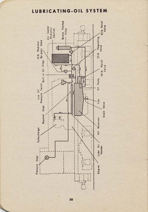
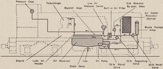
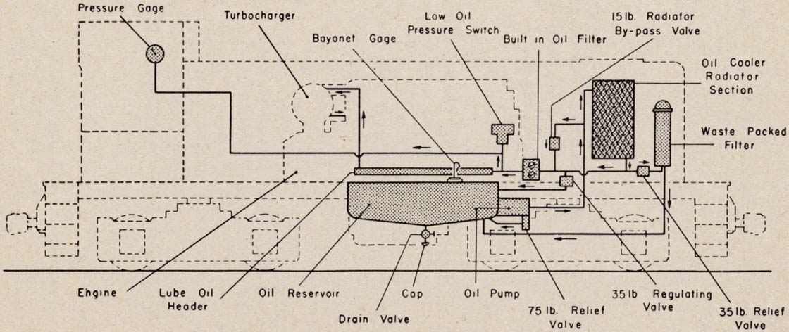
Labels: Pressure Gage, Turbocharger, Bayonet Gage, Low pressure Oil Switch, Built in Oil Filter, 15lb. Radiator By-pass Valve, Oil Cooler Radiator Section, Waste Packed Filter, Engine, Lube Oil Header, Oil Reservoir, Drain Valve, Cap Oil Pump, 75lb. Relief Valve, 35lb. Regulating Valve, 35lb. Relief Valve
FLOW OF LUBRICATING OIL
Lubricating oil is drawn from oil reservoir in base of diesel engine by the lubricating oil pump at front of engine. Pump forces oil through the oil-cooler radiator sections and the waste-packed by-pass filter at front of locomotive.CAPACITY OF SYSTEM
The system holds 80 gallons. The oil from the radiators flows through built-in filters to the oil header in the engine. Oil level can be checked by bayonet gage in the engine base and should be checked on level track with engine running.
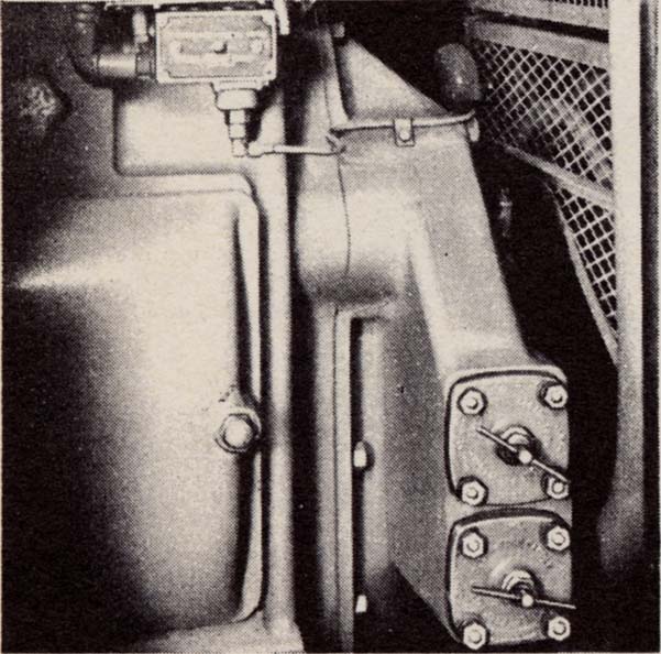
BUILT-IN FILTERS
These filter the lubricating oil just ahead of engine header. When oil pressure drops below 30 lb., rotate handles to clear filters.
PRESSURE GAGE
This should never read less than 26 lb. when diesel engine is running.LOW OIL-PRESSURE SWITCH
When oil pressure drops to 23 lb. this switch stops the diesel engine by opening the governor dump valve. This permits power piston in governor to pull down and shut off fuel supply to engine. The switch resets automatically when oil pressure is restored.
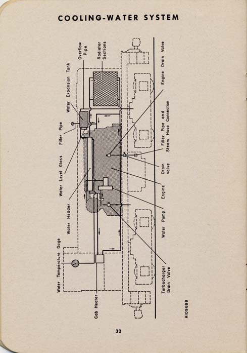
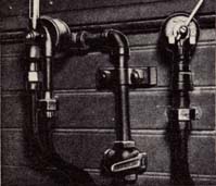
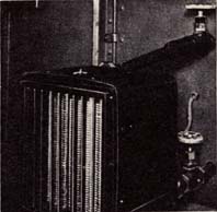
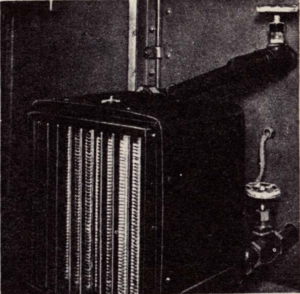
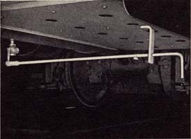
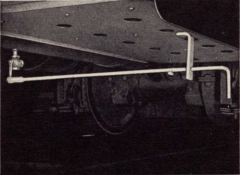
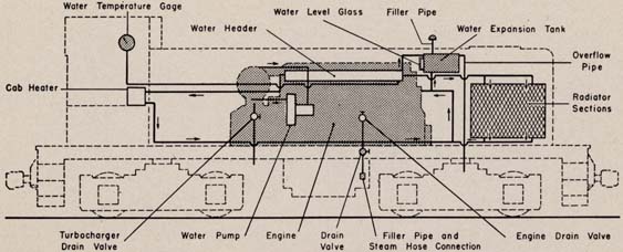
Labels: Water Temperature Gage, Water Header, Water Level Glass, Filler Pipe, Water Expansion Tank, Overflow Pipe, Radiator Sections, Cab Heater, Turbocharger Drain Valve, Water Pump, Engine, Drain Valve, Filler Pipe and Steam Hose Connection, Engine Drain Valve
FLOW OF COOLING WATER
Pump circulates cooling water through engine and cooling system. It is an open system with an expansion tank vented to atmosphere through an overflow pipe.
FILLING SYSTEM
Use water treatment in cooling system. Run water into filler pipe with steam-hose connection, under left center of locomotive, until water appears in overflow pipes or add water through filling hole on top of roof. Capacity: 600-HP, 220 gallons - 1000-HP, 240 gallons.
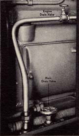
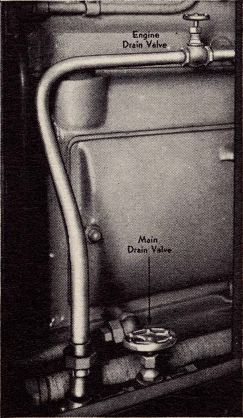
DRAINING SYSTEM
Open engine-block drain valve, main valve in drain and filler pipe, and turbocharger drain valve on 1000-HP switchers. Keep engine-block drain valve closed when engine is running. On locomotives with water heater, open all drain valves in heater pipes.
WATER-TEMPERATURE GAGE
This should read between 150 degrees and 170 degrees F. See page 22.
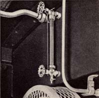
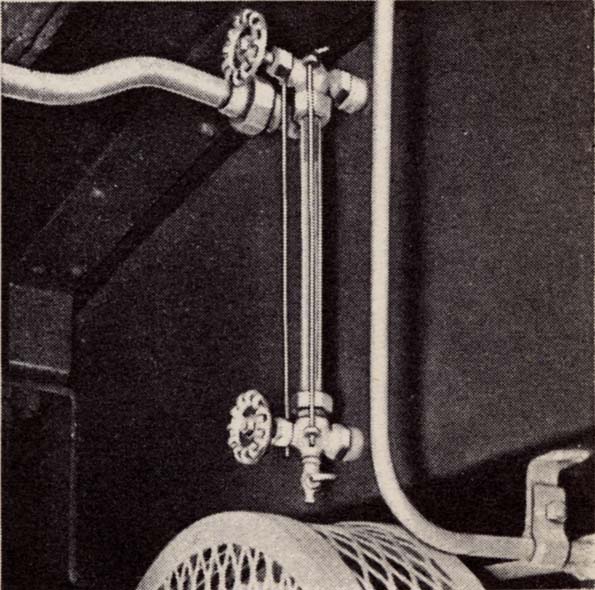
WATER LEVEL GLASS
Sight glass on expansion tank at back of radiator compartment should always show water. Poor water circulation is indicated if water column shows spasmodic changes at a given engine speed.
If locomotive is shut down in freezing weather, connect steam line to water connection under left center of locomotive. Open drain valve and open steam valve slightly to admit a small flow of steam. When steam line is removed, add water to fill system. If steam is not available, drain the system.
CAB HEATER
To operate heater, open water valves to heater and close heater switch.
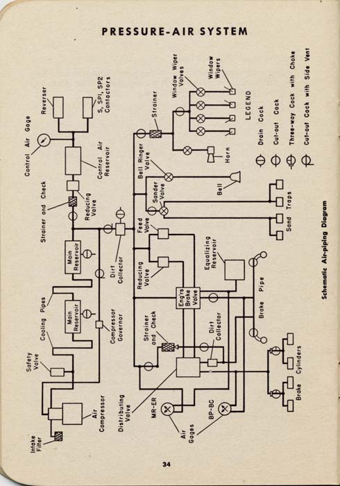
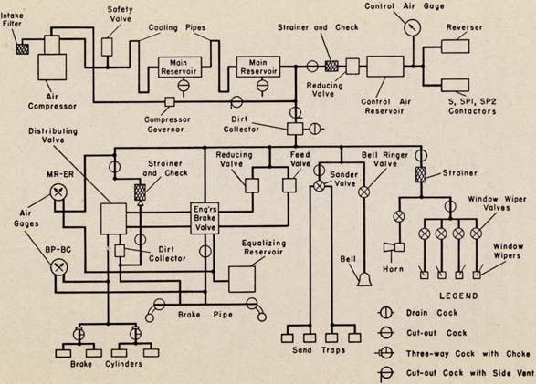
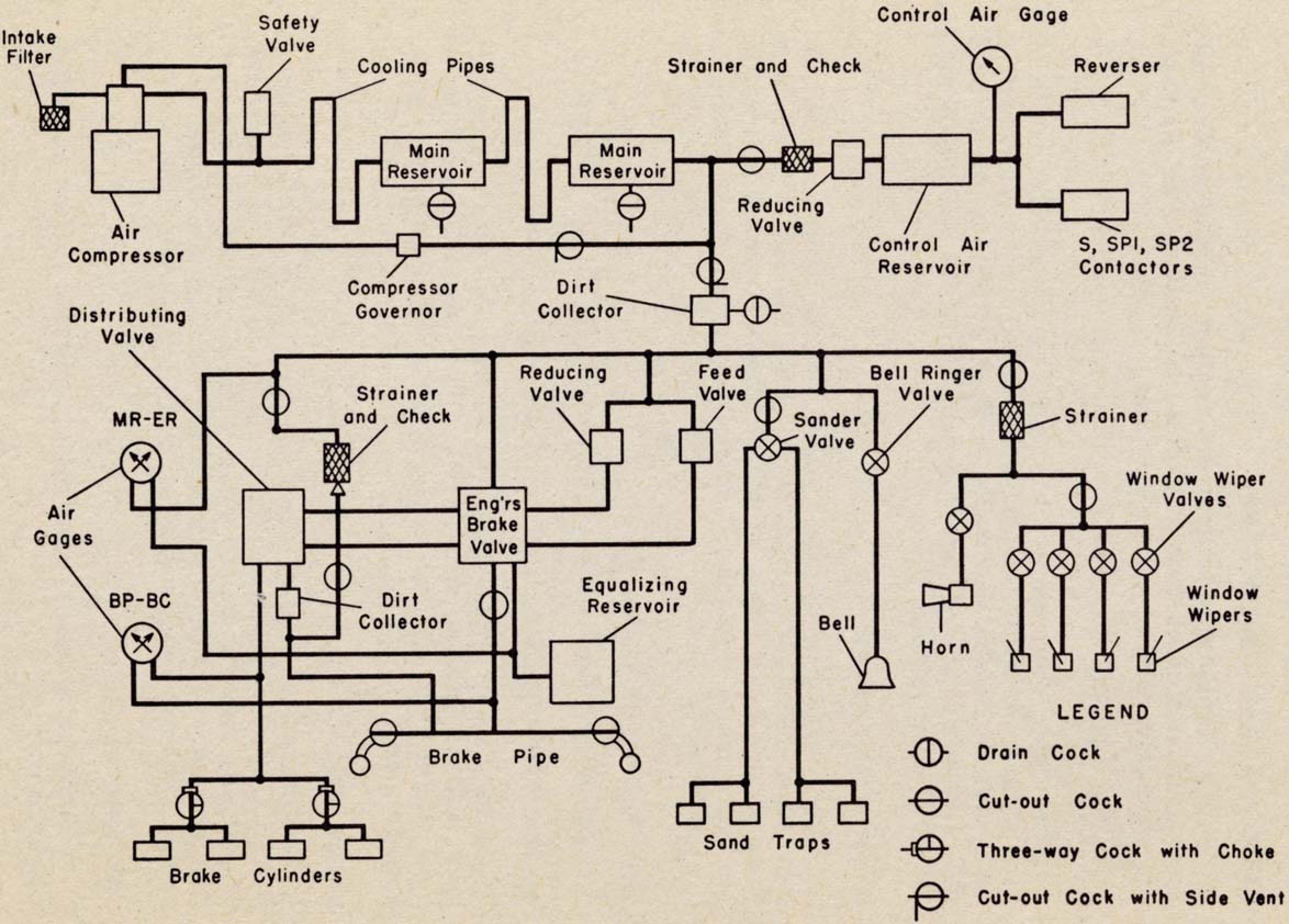
[Schematic Air-Piping Diagram 1x | 4x]
Labels: Intake Filter, Safety Valve, Cooling Pipes, Strainer and Check, Control Air Gage, Reverser, Main Reservoir, Air Compressor, Compressor Governor, Dirt Collector, Reducing Valve, Control Air Reservoir, S/SP1/SP2 Contactors, Distributing Valve, Feed Valve, Sander Valve, Bell Ringer Valve, Strainer, Air Gages, Engineer's Brake Valve, Window Wiper Valves, Equalizing Reservoir, Bell, Horn, Window Wipers, Brake Pipe, Sand Taps, Brake Cylinders, Drain Cock, Cut-out Cock, Three-way Cock with Choke, Cut-out Cock with Side Vent
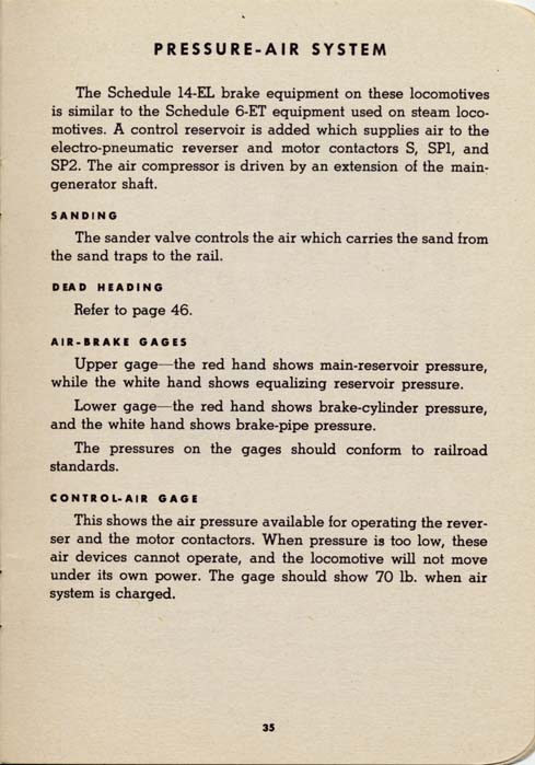
The Schedule 14-EL brake equipment on these locomotives is similar to the Schedule 6-ET equipment used on steam locomotives. A control reservoir is added which supplies air to the electro-pneumatic reverser and motor contactors S, SPl, and SP2. The air compressor is driven by an extension of the main-generator shaft.
SANDING
The sander valve controls the air which carries the sand from the sand traps to the rail.
DEAD HEADING
Refer to page 46.
AIR-BRAKE GAGES
Upper gage - the red hand shows main-reservoir pressure, while the white hand shows equalizing reservoir pressure.
Lower gage - the red hand shows brake-cylinder pressure, and the white hand shows brake-pipe pressure.
The pressures on the gages should conform to railroad standards.
CONTROL-AIR GAGE
This shows the air pressure available for operating the reverser and the motor contactors. When pressure is too low, these air devices cannot operate, and the locomotive will not move under its own power. The gage should show 70 lb. when air system is charged.
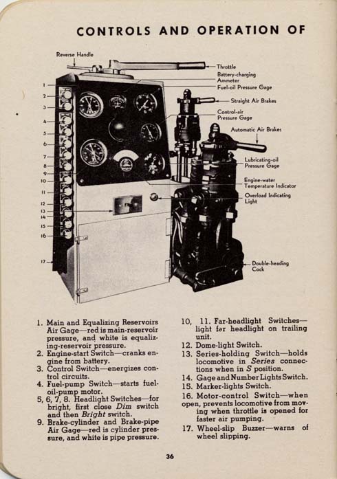
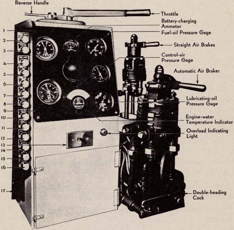
Labels: Reverse Handle, Throttle, Battery-charging Ammeter, Fuel-oil Pressure Gage, Straight Air Brakes, Control-air Pressure Gage, Automatic Air Brakes, Lubricating-oil Pressure Gage, Engine-water Temperature Indicator, Overload Indicating Light, Double-heading Cock
Numbered labels:
Multiple-unit locomotives have slightly different controls, consequently, their operation also differs in a few respects. Operating instructions previously covered in this manual apply except as indicated in this section.
STARTING THE ENGINE
Follow procedure on page 16 except for air pumping. To pump air faster, pull out Motor-control switch, move reverse handle to Forward or Reverse position, and then advance throttle not more than four notches. Some air pressure is required before throttle will operate engine above idling speed.
MOVING THE LOCOMOTIVE
Push in Motor-control switch and follow procedure on page 16 except in step 3 the controller handle has only one position for Forward and Reverse. For normal operation, put Series-holding switch in SP position. Transfer from Series to Series-parallel to Reduced Field as locomotive speed increases and from Reduced Field back to Series-parallel is automatic. Transfer from Series-parallel to Series is made manually by closing throttle, moving Series-holding switch to S position, and reopening throttle. To stay in Series connection, leave Series-holding switch in S position.
OPERATING THE THROTTLE
Advance the notch-type throttle by moving it positively from notch to notch - do not leave it halfway between notches. There are eight power notches in addition to idling notch. When pulling a heavy train, leave throttle a few seconds in each notch when advancing throttle.
OPERATING THE SANDERS
Depress foot switch on floor. Reverse handle automatically controls sanders for forward or backward movement.
Operation with two locomotives in multiple is essentially the same as single-unit operation except that both locomotives are controlled from one engineman's position.
CONNECTING UNITS TOGETHER
Couple two units together and connect air-lines and train-line jumpers. Be sure that each plug is pushed all the way into socket until socket cover latches on plug. To open air-line cocks on trailing unit, move brake-pipe cutout cock to No. 2 position. Move automatic-brake valve to Lap position, move independent brake valve to Running position, and remove both handles. Close throttle. Move reverse handle to Neutral position and remove handle.
STARTING THE ENGINES
Start engines in the same manner as for single-unit operation. Engine in leading unit must be started first. Control switch and Fuel-pump switches must be open on trailing locomotive. Faster air pumping is obtained on both units by advancing throttle on leading unit with Motor-control switch open.
MOVING THE LOCOMOTIVES
Be sure Series-holding switch on trailing unit is in SP position, otherwise this unit will stay in series when switch on leading unit is thrown for normal operation.
SHUTTING DOWN THE LOCOMOTIVES
Opening Fuel-pump switch on leading unit stops both engines. Otherwise steps on page 17 apply.
OPERATING GAGES
While operating, watch trailing unit to see that water temperature doesn't exceed 180 degrees F. Experience will indicate how to set shutters.
OPERATING HEADLIGHTS
Open all headlight switches on trailing units. Push Far-headlight-dim and Far-headlight-bright switches on leading unit to light far headlight on trailing unit.
SHUTTING DOWN ONE ENGINE
Disconnect train-line jumper between units to stop engine on trailing unit. Close all doors, windows, and ventilators. In freezing weather, drain cooling system.
ASCENDING GRADES
If train slows down enough on a grade to light the overload indicator, or, if the locomotive is equipped with a loadmeter and the loadmeter pointer indicates more than 730 amperes, close throttle and then reopen it. On a grade with dips in it, close throttle, put Series-holding switch in S position and reopen throttle. Perform either operation smoothly and quickly to prevent stalling train. When approaching grades that you know will require the above transfer, make transfer before train gets on the grade. Throw switch to SP position when over the grade and train speed increases.
ENGINE WON'T TURN OVER WHEN STARTING BUTTON IS PRESSED
ENGINE TURNS OVER, BUT WON'T FIRE
LOCOMOTIVE WILL NOT MOVE WITH ENGINE RUNNING AND THROTTLE OPEN
If above procedure does not correct condition, call maintainer.
LOCOMOTIVE STAYS AT LOW SPEEDS
This generally indicates that control is not transferring from Series to Series-parallel and or engine output is down. Operate in Series position until condition can be corrected.LOCOMOTIVE MOVES UNDER POWER WITH THROTTLE CLOSED
The throttle switch is probably stuck. To stop locomotive, pull out fuel pump switch and apply brakes.
DIESEL ENGINE STOPS
FUEL PUMP DOESN'T RUN.
LOCOMOTIVE HAS LITTLE POWER WHEN THROTTLE IS OPENED
LUBRICATING-OIL PRESSURE DROPS
AIR PRESSURE DOES NOT BUILD UP
LOSS OF AIR PRESSURE
POORLY MAINTAINED MAIN RESERVOIR PRESSURE
HOT CYLINDER
If one cylinder is receiving too much fuel, its exhaust pipe elbow will be hotter than the others, may even become red hot. Cut out this cylinder and report to maintainer.
CYLINDER NOT FIRING
The exhaust elbow of a cylinder not firing will be cooler than the others. Cut out this cylinder and report to maintainer.
CUTTING OUT FAULTY CYLINDER
Disengage injection-pump cutout pin of that cylinder from the overspeed-trip rack by pulling out cutout pin and turning it. Turn the finger downward until the dog of the cutout pin falls in the slot cut in the injection pump casing. The pin then moves in engaging injection-pump crosshead and holds pump plunger mechanism off injection-pump drive camshaft.
It is permissible to operate at full throttle with one cylinder cut out.
BROKEN FUEL PIPE
If fuel pipe from Bosch pump to nozzle is broken, cut out that cylinder and notify the maintainer.
GROUND RELAY CLOSES
If possible, call the maintainer to inspect generator and traction motors to determine the cause of the ground. It will operate if there is any leakage from high-voltage wiring to locomotive frame. This may occur during a "flashover" which in turn sometimes results from bad wheel slipping, throttle slamming or other careless throttle handling.If the locomotive is in vital transfer or road service, make sure there is no burning smell or serious damage, then reset the relay and proceed. If the relay trips again, open the ground-relay switch, reset the relay, and move the locomotive only far enough to get in the clear.
HOT TRACTION MOTOR SUSPENSION BEARING
This is evidenced by smoke or odor. In switching service, notify the maintainer. In road service, remove the waste, discard charred portions, and repack the bearing, being sure the waste is against the axle. Add plenty of oil, pouring some directly on the waste. After running several miles, inspect the bearing. If it continues to run hot, try backing off the bearing nuts a slight amount.
UNUSUAL NOISES
If the turbocharger or the engine-generator unit gives off an unusual noise, shut down the engine and notify the maintainer.
HIGH ENGINE TEMPERATURES
If the radiator fan will not keep the water temperature normal, check water level, fan shutters, fan belt, and water-pump drive.
An abnormally high reading of thermometer at engineman's position with shutters open indicates faulty circulation or low water. Poor circulation is indicated by spasmodic fluctuations of water column in sight glass on expansion tank at a given engine speed; also by localized heating at various points such as cylinder heads, radiators and water pump.
If water is low and engine has just been worked hard, idle until temperature becomes normal. If possible, add water to the system slowly while the engine is idling.
ENGINE OVERSPEEDS AFTER KICKING CARS
If diesel engine continually overspeeds after the throttle is closed, causing overspeed trip to operate, shut down the engine and notify maintainer. Check Bosch pump rack setting at shutdown position.
ENGINE DIES AFTER KICKING CARS
This usually indicates faulty governor; however, check lubricating-oil system before starting up again.
RUNNING WITH ONE BLOWER DOWN
Load locomotive to only half its full capacity if a traction-motor blower is inoperative. Otherwise, the two traction motors, which it normally ventilates will overheat.
MOVING LOCOMOTIVE WITH ONE TRUCK CUT OUT
Maintainer must first change connections to cut out the motors on defective truck.
Start the diesel engine. Set controller for Series-parallel in desired direction of movement and open throttle to move locomotive. Do not overload the motors on live truck. Move locomotive only far enough to rerail it, or get in the clear.
Maintainer will restore wiring to normal when the trouble has been corrected.
| Railroads |
Home |
Search Local History |
Contact Us |
SCPL Home |
Updated 7/9/01![]()
![]()
This page is Bobby approved and follows the guidelines of the Web Accessibility Initiative for use by the disabled
https://www.schenectadyhistory.org/railroads/manuals/tp107a/index.html updated March 31, 2015
Copyright 2015 Schenectady Digital History Archive — a service of the Schenectady County Public Library